PID Controller
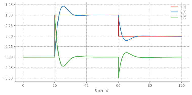
Simulation of a PID controller tracking a step-changing setpoint.
You can also find this example as a single file in the GitHub repository.
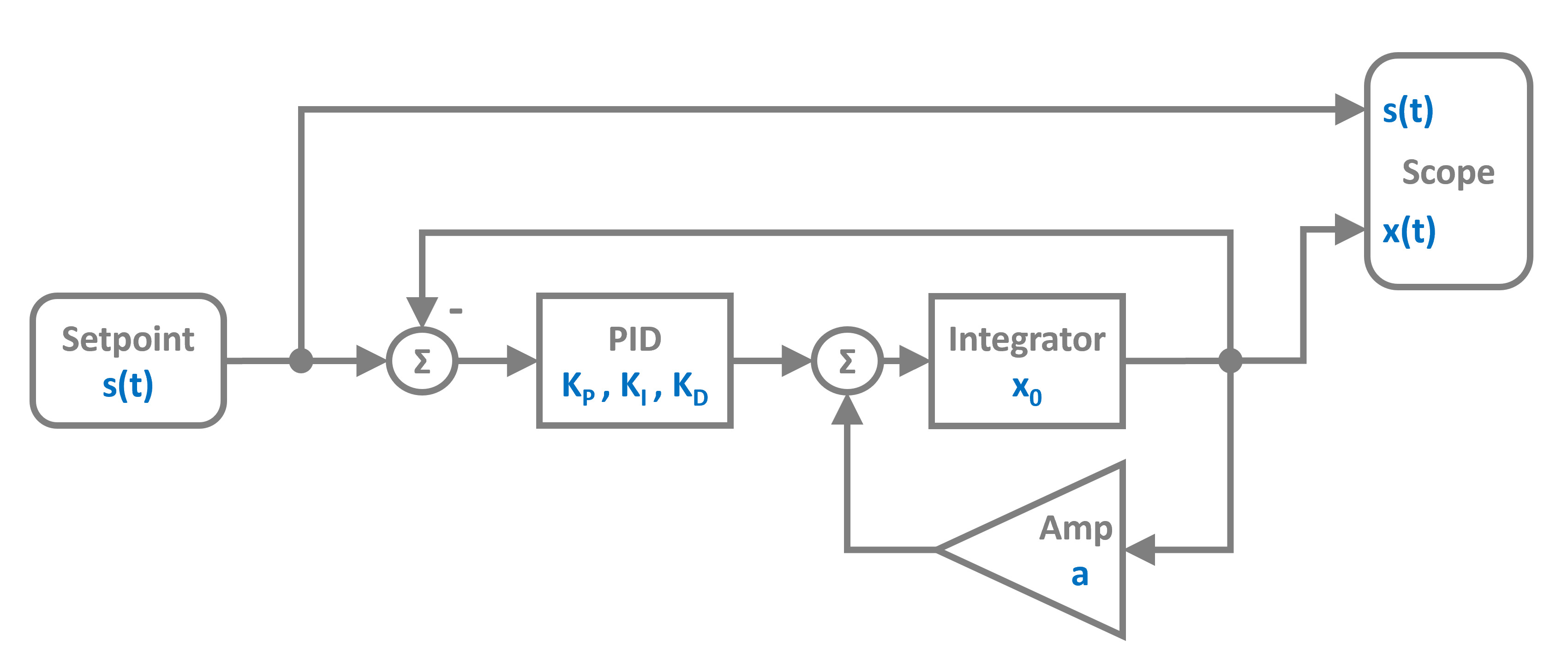
The control system uses a PID controller block that computes the control signal based on the error between setpoint and output. The plant is modeled as an Integrator with a gain. As a block diagram it looks like this:
Import and Setup
First let's import the required classes and blocks:
System Parameters
We define the plant gain and PID parameters.
System Definition
Now we can construct the system by instantiating the blocks we need and collecting them in a list:
The connections form a feedback control loop. The Adder block with signature "+-" computes the error signal by subtracting the plant output from the setpoint.
Simulation Setup and Execution
We initialize the simulation with the RKCK54 solver (Runge-Kutta Cash-Karp 5th order with adaptive step size).
19:04:38 - INFO - LOGGING (log: True)
19:04:38 - INFO - BLOCKS (total: 6, dynamic: 2, static: 4, eventful: 0)
19:04:38 - INFO - GRAPH (nodes: 6, edges: 8, alg. depth: 4, loop depth: 0, runtime: 0.127ms)
19:04:38 - INFO - STARTING -> TRANSIENT (Duration: 100.00s)
19:04:38 - INFO - --------------------   1% | 0.0s<0.3s | 897.6 it/s
19:04:38 - INFO - ####----------------  20% | 0.1s<166:53:10 | 1987.9 it/s
19:04:38 - INFO - ########------------  40% | 0.1s<0.1s | 3578.7 it/s
19:04:38 - INFO - ############--------  60% | 0.2s<45:49:42 | 1735.6 it/s
19:04:38 - INFO - ################----  80% | 0.2s<0.0s | 1683.1 it/s
19:04:38 - INFO - #################### 100% | 0.2s<--:-- | 1663.4 it/s
19:04:38 - INFO - FINISHED -> TRANSIENT (total steps: 455, successful: 291, runtime: 241.16 ms)
Results
Let's plot the setpoint, output, and error signals to see how well the PID controller tracks the setpoint: