Diode Circuit
Simulation of a diode circuit demonstrating nonlinear algebraic loop solving.
You can also find this example as a single file in the GitHub repository.
Circuit Description
The circuit consists of:
- A sinusoidal voltage source: MATHINLINE1ENDMATH V
- A resistor: MATHINLINE2ENDMATH Ω
- A diode with exponential I-V characteristic
Diode Model
The diode current follows the Shockley equation:
MATHDISPLAY0ENDMATH
Where:
- MATHINLINE3ENDMATH A (saturation current)
- MATHINLINE4ENDMATH mV (thermal voltage at room temperature)
- MATHINLINE5ENDMATH is the diode voltage
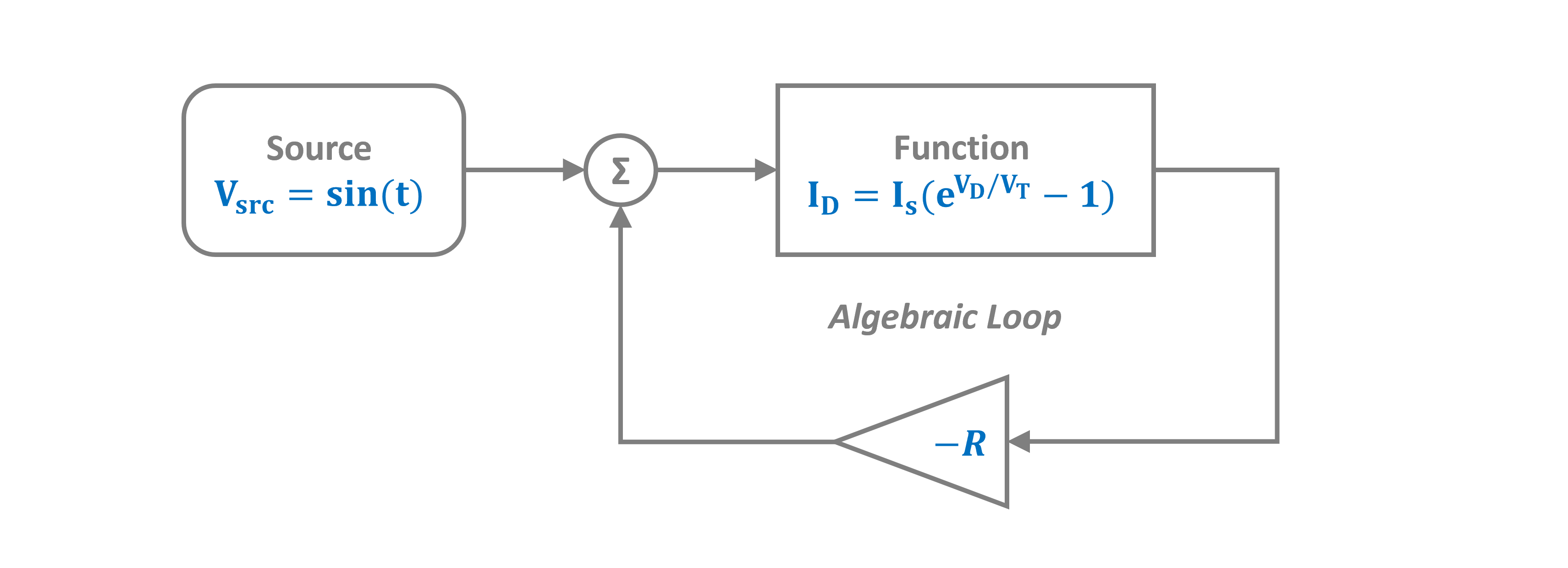
The Algebraic Loop
Applying Kirchhoff's Voltage Law (KVL):
MATHDISPLAY0ENDMATH
Substituting the diode equation creates a nonlinear algebraic loop:
MATHDISPLAY1ENDMATH
PathSim solves this nonlinear equation automatically at each timestep using accelerated fixed-point iteration.
This example demonstrates a nonlinear algebraic loop. The Function block implements the diode characteristic, and PathSim solves the implicit circuit equations automatically.
Circuit Parameters
Connections
The connections implement Kirchhoff's laws:
- The adder computes: MATHINLINE0ENDMATH
- The resistor voltage is: MATHINLINE1ENDMATH
- The diode current depends on: MATHINLINE2ENDMATH (creating the loop)
Simulation
We use a tight convergence tolerance (tolerance_fpi=1e-12) to ensure accurate solution of the nonlinear algebraic equation.
12:43:37 - INFO - LOGGING (log: True)
12:43:37 - INFO - BLOCKS (total: 6, dynamic: 0, static: 6, eventful: 0)
12:43:37 - INFO - GRAPH (nodes: 6, edges: 7, alg. depth: 1, loop depth: 3, runtime: 0.138ms)
12:43:37 - INFO - STARTING -> TRANSIENT (Duration: 2.00s)
12:43:37 - INFO - --------------------   1% | 0.0s<0.9s | 228.5 it/s
12:43:38 - INFO - ####----------------  20% | 0.1s<0.2s | 722.2 it/s
12:43:38 - INFO - ########------------  40% | 0.1s<0.0s | 17267.6 it/s
12:43:38 - INFO - ############--------  60% | 0.2s<0.2s | 445.5 it/s
12:43:38 - INFO - ################----  80% | 0.2s<0.0s | 20027.4 it/s
12:43:38 - INFO - #################### 100% | 0.2s<--:-- | 11163.2 it/s
12:43:38 - INFO - FINISHED -> TRANSIENT (total steps: 200, successful: 200, runtime: 242.78 ms)
Results: Voltage Waveforms
The plots show:
- v_source (blue): Input sinusoidal voltage
- v_diode (orange): Voltage across the diode
Notice how the diode voltage is:
- Clamped near ~0.7V during forward bias (positive half-cycle)
- Follows the source during reverse bias (negative half-cycle, diode is off)
This is the classic diode rectifier behavior!


Diode Current
Let's examine the diode current to see the rectification more clearly.

Diode I-V Characteristic
We can also visualize the diode's I-V characteristic by plotting current vs. voltage.
